Sunbelt Stud Welding
1-800-462-9353
www.sunbeltstudwelding.com

Automated Robotic Stud Welding Systems

Robotic stud welding systems deliver high-speed, structural repeatability, and fractions of an inch precision to high-volume manufacturing environments. Robotic cells with stud welders automate stud attachment, using industrial robots, programmable welding controllers, and automatic stud feeding technology. Sunbelt Stud Welding supplies the stud welding power sources, automatic stud feeders, welding heads, and control components required to integrate stud welding into industrial robotic cells. Our automation solutions support Capacitor Discharge (CD), Drawn Arc, and Short Cycle stud welding for high-volume manufacturing, OEM production, and industrial fabrication.
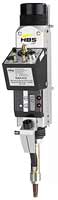
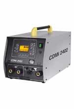
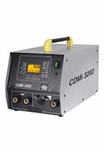
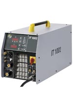
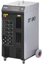
Stud Welding Components for Robotic Integration

What Is a Robotic Stud Welding System?

A robotic stud welding system combines an industrial robot, stud welding power source, automatic stud feeder, welding head, and programmable controls into a fully automated manufacturing cell. The system performs repeatable stud welds with precise positioning, controlled welding parameters, and high production throughput for OEM and industrial fabrication.

Material Compatibility

Carbon & Mild Steel
Stainless Steel
Galvanized Steel
Aluminum
CD: M3 to M10 | DA: M3 to M12
AUTOMATED ROBOTIC WELDING CELL SYSTEM ARCHITECTURE
Component Functions
  • Industrial Robot: Positions the welding head using programmed coordinates
  • Stud Welding Machine: Provides controlled electrical output for Arc or Capacitor Discharge welding processes
  • Automatic Stud Feeder: Supplies individual studs through pneumatic or mechanical feed systems
  • Welding Head: Controls stud positioning, lift movement, and weld execution
  • PLC / Controller: Synchronizes robot motion, welding sequence, and production signals
  • HMI Interface: Allows parameter setup, diagnostics, and operator monitoring
  • Safety System: Controls guarding, emergency stops, and machine interlocks
TECHNICAL SPECIFICATIONS
Note Actual specifications vary depending on the selected stud welding machine, welding process, and automation level.
Welding Process Capacitor Discharge (CD), Drawn Arc (DA), Short Cycle Drawn Arc (SC)
Robot Configuration 6-axis industrial robotic arm
Stud Diameter Range Application dependent; commonly, CD: 14 ga to 3/8” (M3 to M10) | Drawn Arc: 1/8” to 1/2” (M3 to M12)
Stud Length Range ⅛” to 3” (custom escapements available for extended lengths)
Welding Control Programmable current, voltage, and weld timing
Feeding Mechanism Continuous pneumatic blow-feed system with optical stud presence sensing
Position Accuracy Dependent on robot repeatability and fixture design
Repeatability / Accuracy Robot Pose Repeatability: ±0.002”; Stud Placement Accuracy: ±0.008”
Communication Digital I/O, PLC, Industrial EtherNet/IP, DeviceNet, EtherCAT
Programming Robot controller, PLC, HMI interface
Operation Mode Single-cell or fully integrated production line
Quality Control Weld parameter monitoring and production tracking
INDUSTRIAL APPLICATIONS
Industry Applications
Automotive Battery trays, chassis components, brackets, grounding studs
Structural Steel Shear connectors, anchor studs, steel fabrication
Heavy Equipment Construction machinery, agricultural equipment, industrial frames
HVAC & Appliances Insulation pins, panels, mounting components
Electrical Manufacturing Enclosures, grounding points, switchgear assemblies
Transportation Railcars, trailers, commercial vehicles
General Fabrication OEM production and custom metal assemblies

FAQs

A robotic stud welding system is an automated setup that combines an industrial robot, stud welding machine, automatic feeder, and control system to perform repeatable stud welds with minimal operator involvement.

A robotic stud welding system positions the welding head, feeds a stud automatically, executes the programmed welding cycle, and verifies process parameters before moving to the next weld location.

Yes. Stud welding can be fully automated using industrial robots, CNC systems, automatic feeders, and programmable welding controllers for high-volume manufacturing.

Yes. The correct configuration depends on the application, including stud diameter, material thickness, weld strength requirements, and production goals.

Common applications include automotive manufacturing, heavy equipment, HVAC, electrical equipment, transportation, and OEM production.

System accuracy depends on the robot, fixture design, calibration, and application requirements. Properly engineered systems provide highly repeatable stud placement throughout continuous production.

Yes. Robotic stud welding systems can handle studs from M3–M25 (or 1/8"–1") in drawn-arc welding, and up to ~3/8" (10mm) in CD welding, automatically adjusting current (300–3000A) and weld time per diameter. Interchangeable chucks and gun tooling let one automated welding system run mixed diameters without manual recalibration.

Yes. Vision systems locate weld points and verify stud position within ±0.1–0.5mm tolerance before and after welding, catching misalignment in real time. This is crucial in high-mix or high-tolerance runs where even 1–2mm deviation causes part rejection.

Yes. Automated welding robot machines track weld log current, voltage, arc time (typically 0.1–0.6 sec for drawn-arc, 1–6 milliseconds for CD), and plunge depth per weld, flagging deviations beyond ±5–10% tolerance for 100% weld traceability.

Weld cycles themselves often take less than a second of ARC time; overall speed depends on part handling and stud size. CD welding cycles run 1–6 milliseconds of arc time; drawn-arc runs 0.1–0.6 seconds. Including robot positioning, cells commonly achieve 300–1,200 welds per hour depending on stud size and part handling.

Yes. Aluminum studs (typically 3mm–10mm diameter) are welded via CD stud welding using 1–6 millisecond ARC times and 500–3000 microfarad capacitor banks, minimizing heat input and limiting distortion in 1–3mm-thick sheet.

Oftentimes, yes. An existing robotic welding cell can be retrofitted with a stud welding gun and power supply rather than replaced entirely, provided the robot's payload, reach, and controller can integrate with the stud welder.

Why Choose Robotic Stud Welding?

  • Handles Complex 3D Weld Patterns: Follows programmed paths across curved or multi-plane surfaces for accurate placement, even with dozens of weld points.
  • Eliminates Manual Positioning: Studs are located, aligned, and welded automatically, removing operator-to-operator variation in angle, pressure, and placement.
  • Integrates with Conveyors and Production Lines: Robotic cells slot directly into existing production flow, synced with conveyors, part fixtures, and upstream/downstream stations, making stud welding one continuous step instead of a separate manual task.
  • Enables Lights-out Manufacturing: With vision checks and quality monitoring in place, cells can run unattended shifts without quality loss.
  • Supports Multiple Product Variants: Programmable weld schedules switch between stud diameters and materials without retooling the line.
  • Reduces Operator Fatigue: Withdraws repetitive manual work, keeping output consistent from the first weld to the last.
  • Improves Repeatability: Automated current, plunge, and timing control keep every weld within tight tolerance.

Benefits Of Robotic Stud Welding Automation

Integrating a robot stud welding machine into a production line improves manufacturing efficiency by reducing manual operations and maintaining consistent weld quality throughout high-volume production.

  • Fractions of an inch positional accuracy
  • 100% process traceability
  • Elimination of surface defect rework
  • Non-stop operational duty cycle
  • Reduced material scrap rates
  • Better safety protocols
  • Simplified quality control
  • Continuous manufacturing capability

Robotic Stud Welding vs. CNC Stud Welding

Factor Robotic Stud Welding CNC Stud Welding
Motion 6-axis articulated arm, ±0.02–0.05mm repeatability Linear X/Y/Z gantry, typically 2–4 axes
Work envelope Reaches 1,200–3,100mm radius; welds at compound angles Fixed rectangular travel (X/Y/Z stroke), flat-plane access only
Part geometry Curved, angled, multi-plane surfaces; up to 50+ weld points per part Flat panels, tubes, or repetitive linear patterns
Changeover Reprogram via offline path software; supports 10+ part variants per cell Requires new fixture/program per part family; slower changeover
Cycle speed 300–1,200 welds/hour (drawn-arc); 1,200–2,500/hour (CD) depending on positioning 400–1,500 welds/hour on fixed layouts; faster on identical repeat parts
Stud diameter range M3–M25 drawn-arc; up to 10mm CD Typically M4–M20, matched to fixed tooling
Payload/tooling Gun payload 2–5 kg; tool-change capable for mixed studs Fixed gun mount, less tooling flexibility
Investment $150K–$400K+ per cell (robot + welder + vision + integration) $60K–$180K per station (welder + fixed axis frame)
Best fit Automotive brackets, appliance housings, structural steel with varied geometry High-volume flat panels, tube stock, standardized sheet metal parts
ROI driver Flexibility across part changes; lower changeover cost per SKU Lower per-unit cost on long, unchanging production runs

Need A Custom Robotic Stud Welding Solution?

Whether you're designing a new robotic manufacturing cell or integrating stud welding into an existing automation line, our engineers can recommend the right combination of welding power source, feeder, welding head, and controls for your application.

Call: 713-939-8903